OEM Manufacturer Sfp Sr Sx - 2.5GBASE-BX SFP 1550nm-TX 1490nm-RX 80km Hi-Optel HWTR-48-054778133F module – Hi-optel
OEM Manufacturer Sfp Sr Sx - 2.5GBASE-BX SFP 1550nm-TX 1490nm-RX 80km Hi-Optel HWTR-48-054778133F module – Hi-optel Detail:
Features
● SFP Multi-source Package with LC Receptacle
● Up to 2.5Gb/s Data Links
● Up to 80km on 9/125µm SMF
● Single +3.3V Power Supply
● Hot-Pluggable
● Compliant with ITU-T G.957
● Eye Safety Designed to Meet Laser Class1, Compliant with IEC60825
● Monitoring Interface Compliant with SFF-8472
● Compliant with Bellcore TA-NWT-000983
● Operating Case Temperature
Standard(X=1):0℃~+70℃
Industrial(X=2):-40℃~+85℃
● RoHS Compliant Products
Pin Description
|
Pin |
Symbol |
Name/Description |
Ref |
|
1 |
VEET |
Transmitter Ground(Common with Receiver Ground) |
1 |
|
2 |
TFAULT |
Transmitter Fault.Low normal operation,High Fault indication | |
|
3 |
TDIS |
Transmitter Disable.Laser output disabled on high or open |
2 |
|
4 |
MOD_DEF(2) |
Module Definition 2.Data line for Serial ID |
3 |
|
5 |
MOD_DEF(1) |
Module Definition 1.Clock line for Serial ID |
3 |
|
6 |
MOD_DEF(0) |
Module Definition 0.Grounded within the moudle |
3 |
|
7 |
Rate Select |
No connection required | |
|
8 |
LOS |
Loss of Signal indication.Logic 0 indicates normal operation. |
4 |
|
9 |
VEER |
Receiver Ground(Common with Transmitter Ground) |
1 |
|
10 |
VEER |
Receiver Ground(Common with Transmitter Ground) |
1 |
|
11 |
VEER |
Receiver Ground(Common with Transmitter Ground) |
1 |
|
12 |
RD- |
Receiver Inverted DATA out.AC Coupled | |
|
13 |
RD+ |
Receiver Non-inverted DATA out.AC Coupled | |
|
14 |
VEER |
Receiver Ground(Common with Transmitter Ground) |
1 |
|
15 |
VCCR |
Receiver Power Supply | |
|
16 |
VCCT |
Transmitter Power Supply | |
|
17 |
VEET |
Transmitter Ground(Common with Receiver Ground) |
1 |
|
18 |
TD+ |
Transmitter Non-inverted DATA in.AC Coupled | |
|
19 |
TD- |
Transmitter Inverted DATA in.AC Coupled | |
|
20 |
VEET |
Transmitter Ground(Common with Receiver Ground) |
1 |
Notes:
1. Circuit ground is internally isolated from chassis ground.
2. Laser output disabled on TDIS >2.0V or open, enabled on TDIS <0.8V.
3. Should be pulled up with 4.7k – 10kohms on host board to a voltage between 2.0V and 3.6V.
MOD_DEF(0) pulls line low to indicate module is plugged in.
4. LOS is open collector output. Should be pulled up with 4.7k – 10kohms on host board to a voltage between 2.0V and 3.6V. Logic 0 indicates normal operation; logic 1 indicates loss of signal.
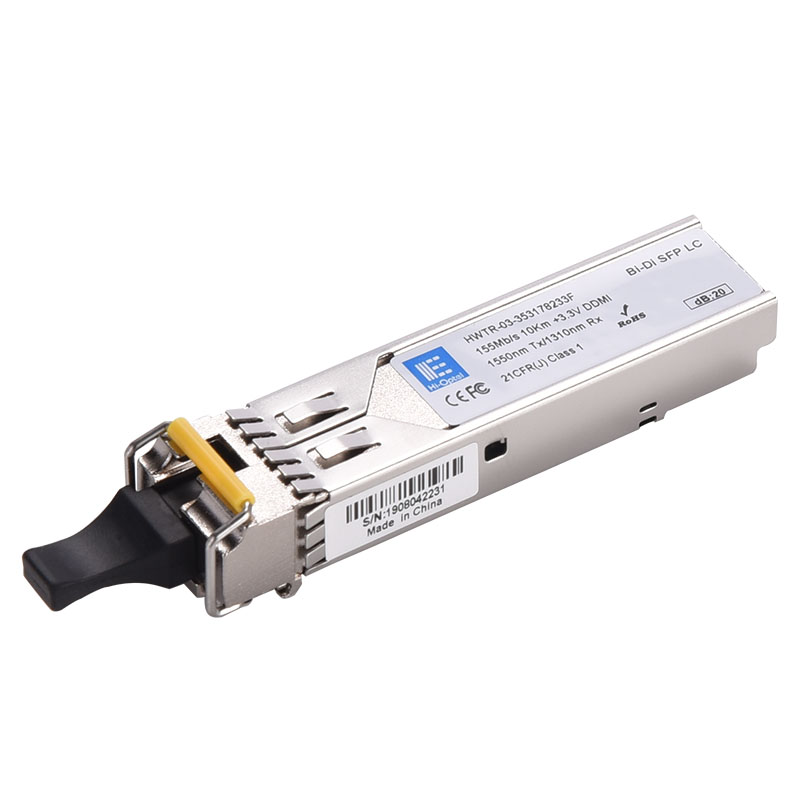
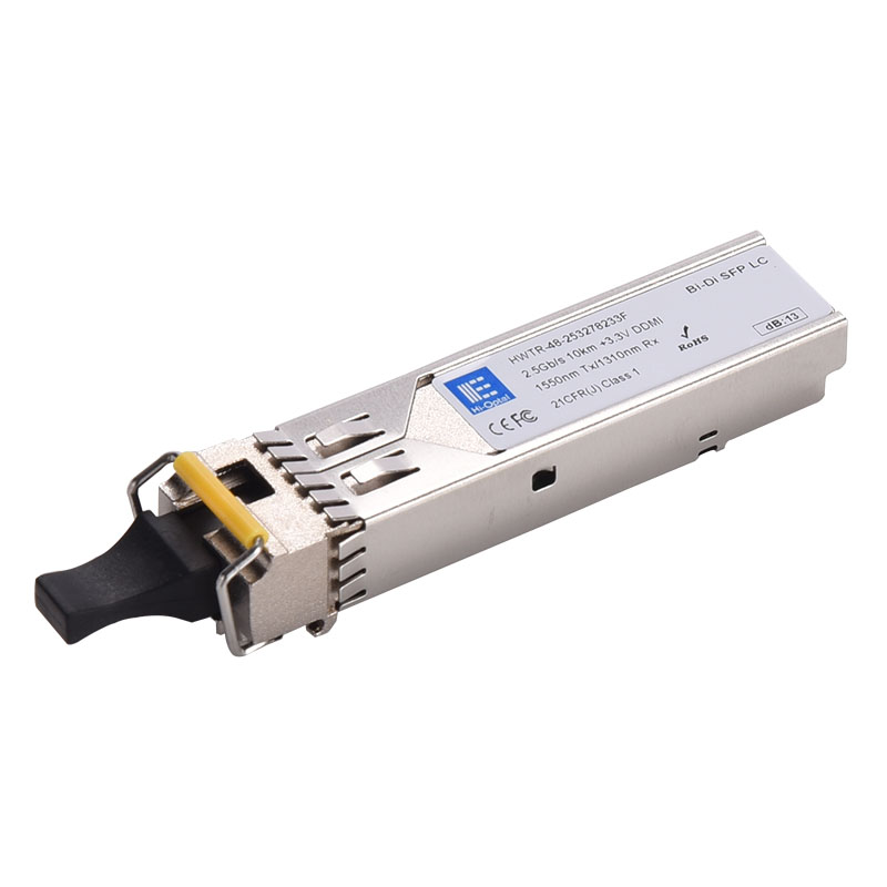
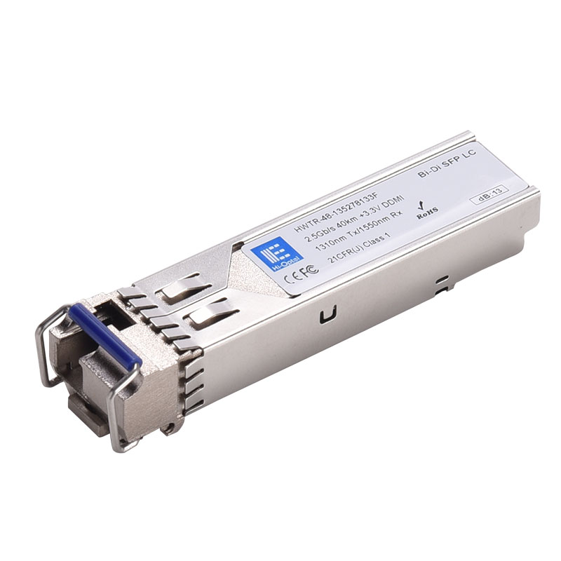
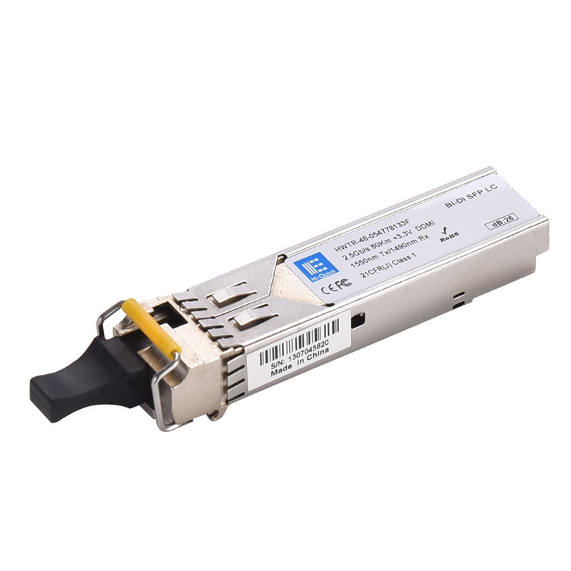
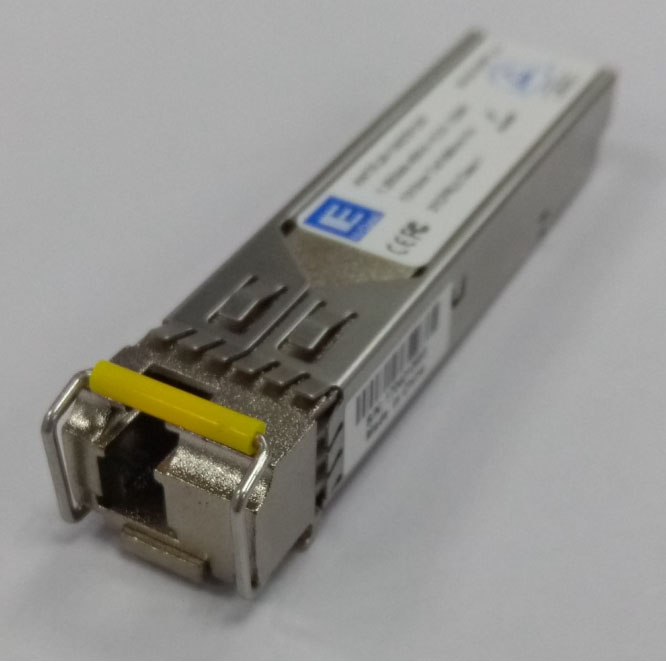
Product detail pictures:
Related Product Guide:
We believe that long expression partnership is often a result of top of the range, value added service, prosperous encounter and personal contact for OEM Manufacturer Sfp Sr Sx - 2.5GBASE-BX SFP 1550nm-TX 1490nm-RX 80km Hi-Optel HWTR-48-054778133F module – Hi-optel , The product will supply to all over the world, such as: Philippines, Azerbaijan, Mauritius, We've been proud to supply our products and solutions to every auto fan all around the world with our flexible, fast efficient services and strictest quality control standard which has always approved and praised by customers.
The customer service staff is very patient and has a positive and progressive attitude to our interest, so that we can have a comprehensive understanding of the product and finally we reached an agreement, thanks!